Ac Battery Wiring Diagram : Battery Charger Ac Power Plugs And Sockets Electrical Switches Electrical Wires Cable Wiring Diagram Usb Electronics Electrical Wires Cable Electronic Device Png Pngwing. Draw in green the horn control circuit from the battery to ground. Wiring pv panel to charge controller, 12v battery & 12vdc load. If this is the case, connect the two browns we mentioned for terminal 6 into terminal 5 instead. To review a wiring diagram, initially you have to understand just what essential components are included in a wiring diagram, and which photographic symbols are made use of to represent them. Then connect the purple from the light switch into terminal 5 also.
Edn resurrecting a 6 amp battery charger paul rako. 2000 honda vt 1100 c2 shadow sabre wiring diagram. Kz650 wiring harness auto electrical wiring diagram. Ac neutral (white) to converter main breaker hold down ac hot (black) to converter. Draw in red the horn circuit from the battery to ground.
Ac Plug Wiring Mazda Parts All Wiring Diagram Route from images-na.ssl-images-amazon.com In this simple solar panel wiring tutorial, we will show how to connect a solar panel to the solar charge controller, battery and direct dc load according to the rating. The usual components in a wiring diagram are ground, power supply, cord as well as link, outcome tools, buttons, resistors, logic gate, lights, etc. A 2 kw, 4 kw, and 8 kw system are shown and include the solar panels, combiner boxes, charge controller (s), power inverter (s), battery bank, shunt & meter circuits, ac breaker panel, and ac generator wiring. The red wire represents the positive battery terminal and the pink wire represents the bare metal drain wire. , start & charging wiring diagram: How will the circuit be affected if there were. The shown position of the relays are in the n/c directions, meaning the relays are not powered, which will obviously be in the absence of the mains ac input. 2000 honda vt 1100 c2 shadow sabre wiring diagram.
Get to know your truck's wiring.
Below is a rv electric wiring diagram or schematic including the converter and inverter for a generic rv. Bl battery bussing 25 bm bodybuilder module 2016 26. • do not short circuit batteries this can cause fire or explosion. The usual components in a wiring diagram are ground, power supply, cord as well as link, outcome tools, buttons, resistors, logic gate, lights, etc. Napa battery charger repair parts. Typical electrical problems include bad batteries, alternators, and starters, along with blown fuses and bad battery cables. Handy hint ** if you have an electronic wiring loom you will not have a purple. We've changed the diagram a bit now to show the start battery running through our new marine battery switch. Design your system quickly with our. Draw in red the horn circuit from the battery to ground. If not, the arrangement won't function as it should be. 4a8b7 36 volt powerwise charger wiring diagram digital resources. Each part should be set and connected with different parts in specific manner.
Understanding toyota wiring diagrams worksheet #3 1. I have made several changes over the years. Typical electrical problems include bad batteries, alternators, and starters, along with blown fuses and bad battery cables. + ac neutral in (white) ac ground in (green) battery neg. The ac41 on the left has the drain wire directly connected to the black battery wire.
Diagram Dewalt 18v Diagram Full Version Hd Quality 18v Diagram Milsdiagram Villascorzi It from wiringall.com • do not short circuit batteries this can cause fire or explosion. Formula 382 fasttech cabin stereo wiring schematic diagrams.pdf 98.2kb download. Keep in mind that ac load is not connected in this pv panel wiring tutorial which needs extra equipment such as ups and inverter to convert the solar panel and. Rv converter wiring diagram in camper plug battery images. Edn resurrecting a 6 amp battery charger paul rako. Typical electrical problems include bad batteries, alternators, and starters, along with blown fuses and bad battery cables. To review a wiring diagram, initially you have to understand just what essential components are included in a wiring diagram, and which photographic symbols are made use of to represent them. The shown position of the relays are in the n/c directions, meaning the relays are not powered, which will obviously be in the absence of the mains ac input.
Formula 382 fasttech cabin stereo wiring schematic diagrams.pdf 98.2kb download.
We've changed the diagram a bit now to show the start battery running through our new marine battery switch. • always use insulated tools when working with electricity and batteries. Edn resurrecting a 6 amp battery charger paul rako. 12 volt schumacher battery charger schematic. The red wire represents the positive battery terminal and the pink wire represents the bare metal drain wire. Below is a collection of quick reference diagrams on hooking up multiple 6 volt and 12 volt batteries to create 6v, 12v, 24v, 48v etc as required for energy storage systems commonly found in residential and off grid solar, hydro and wind systems. The shown position of the relays are in the n/c directions, meaning the relays are not powered, which will obviously be in the absence of the mains ac input. Bl battery bussing 25 bm bodybuilder module 2016 26. Looking at the diagram we can see that the unit requires two relays, however one of them is a dpdt relay while the other one is an ordinary spdt relay. Design your system quickly with our. To review a wiring diagram, initially you have to understand just what essential components are included in a wiring diagram, and which photographic symbols are made use of to represent them. If not, the arrangement won't function as it ought to be. This differs a schematic layout, where the plan of the parts' interconnections on the diagram generally does not represent the parts' physical areas in the completed device.
Then connect the purple from the light switch into terminal 5 also. The following basic wiring diagrams show how batteries, battery switches, and automatic charging relays are wired together from a simple single battery / single engine configuration to a two engine, one generator, and four battery bank system. A 2 kw, 4 kw, and 8 kw system are shown and include the solar panels, combiner boxes, charge controller (s), power inverter (s), battery bank, shunt & meter circuits, ac breaker panel, and ac generator wiring. These example system diagrams will show how to connect the components of a solar energy system. Wiring diagram ws= white sw = black ro = red br = brown gn = green bl = blue gr = grey li = lilac ge = yellow ignition/starter switch, main fuse or = orange rs = pink audi a4 no.
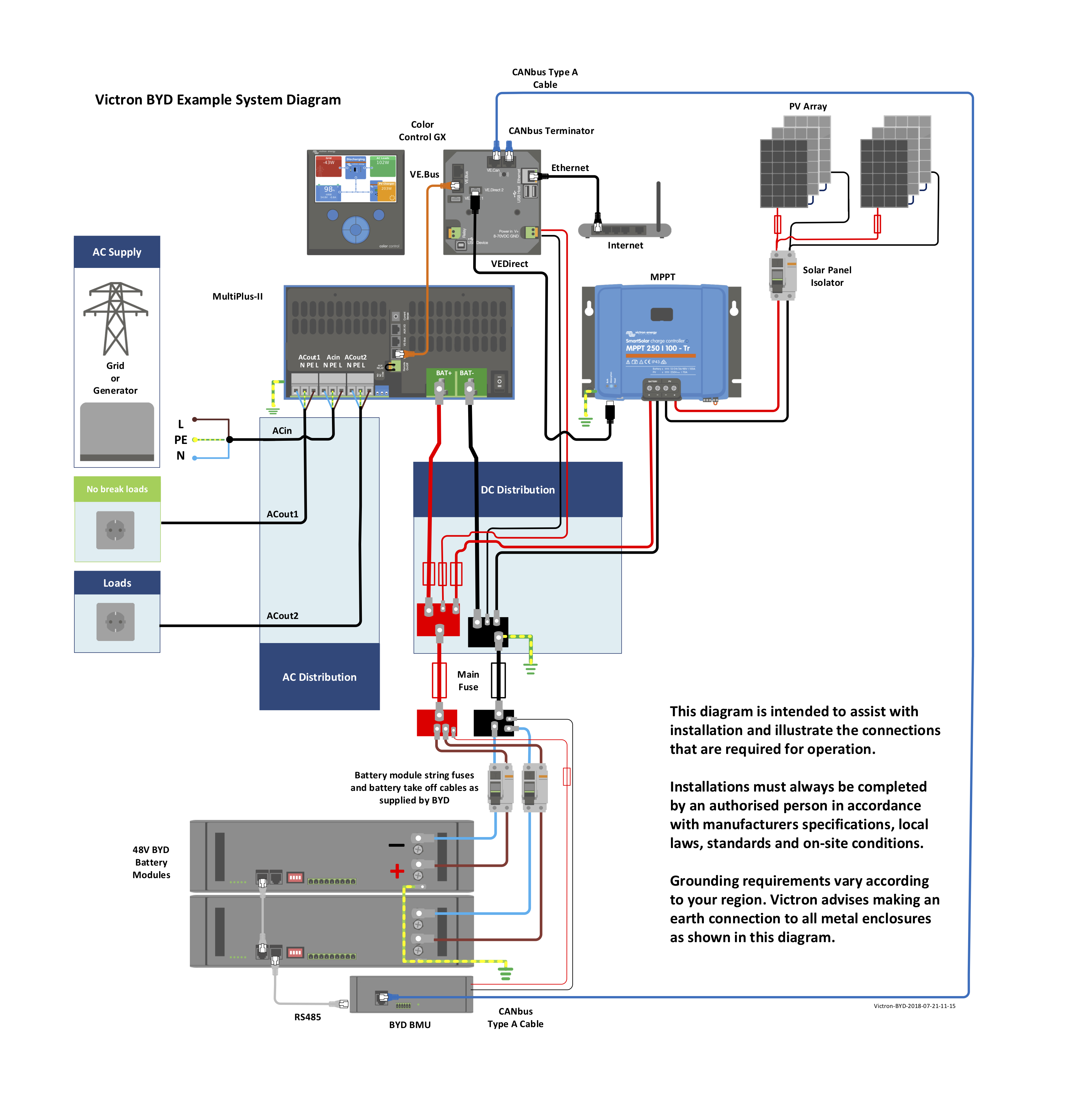
Victron Byd Victron Energy from www.victronenergy.com Bl battery bussing 25 bm bodybuilder module 2016 26. Design your system quickly with our. Draw in blue the part of the circuit that is common to both the control and load (horn) circuit. For one, i've installed an inverter and smart charger, both of which require heavy gauge wiring to the house batteries. To review a wiring diagram, initially you have to understand just what essential components are included in a wiring diagram, and which photographic symbols are made use of to represent them. The red wire represents the positive battery terminal and the pink wire represents the bare metal drain wire. These example system diagrams will show how to connect the components of a solar energy system. Transformer wiring diagram battery charger wiring diagram.
Handy hint ** if you have an electronic wiring loom you will not have a purple.
Formula 382 fasttech cabin stereo wiring schematic diagrams.pdf 98.2kb download. A wiring diagram normally gives info concerning the family member placement and plan of devices and terminals on the gadgets, to help in building or servicing the gadget. The usual components in a wiring diagram are ground, power supply, cord as well as link, outcome tools, buttons, resistors, logic gate, lights, etc. • always use insulated tools when working with electricity and batteries. Draw in blue the part of the circuit that is common to both the control and load (horn) circuit. The shown position of the relays are in the n/c directions, meaning the relays are not powered, which will obviously be in the absence of the mains ac input. How will the circuit be affected if there were. We've changed the diagram a bit now to show the start battery running through our new marine battery switch. These systems are also common in rvs which meshes with a project i'm currently gearing up for. , start & charging wiring diagram: Ace novella verona 6 berth 2 3jtd 16v 6 metre long 6 berth with. • ac and dc voltages are dangerous and harmful. Draw in green the horn control circuit from the battery to ground.